Author: Junwei Zhang, Tencent Cloud Architecture and Platform Department
Background and Introduction
Tencent Gateway (TGW) is the first access point for Internet traffic going over the Tencent network, which consolidates multiple applications: elastic IP (EIP), Cloud Load Balancer (CLB) etc. EIP is the gateway between Tencent’s Virtual Private Cloud (VPC) and the public network. Along with the continued growth of Tencent’s service, EIP faces more and more challenges. CLB is a secure and fast traffic distribution service. Inbound traffic can be automatically distributed to multiple Cloud Virtual Machine (CVM) instances in the cloud via CLB.
EIP has two major functions:
- Switching and forwarding between Underlay & Overlay networks
- Rate shaping based on EIP.
EIP X86 Based Server Cluster Solution Architecture
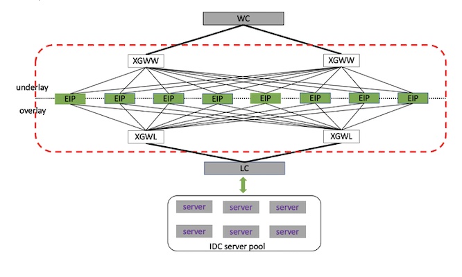
Tencent’s original solution for EIP was a x86-based server cluster. Figure 1 below shows the topology. EIP gateways work as internal and external traffic converters and are logically located between the Tencent IDC and the public network.
 Figure 1 – EIP Topology
EIP is a stateless gateway. Tencent designed its EIP solution with two considerations:
- Horizontal Extensibility: The machines in the cluster are peer-to-peer, and each machine has the full configuration information of the entire cluster. This allows traffic to be forwarded to any device for processing. The number of machines in the cluster can be dynamically scaled as traffic fluctuates.
- Disaster Recovery & Backup: In order to support disaster recovery in the Availability Zone (AZ) equipment room, usually 8 machines in each cluster are divided into two groups, and each group of 4 machines is placed in one equipment room. These two groups of machines realize mutual disaster recovery backup by publishing large and small network segments. Under normal circumstances, the traffic of one EIP will only go to four servers in one computer room. When the network of the computer room is abnormal, the traffic will be directed to the four servers in another computer room of the cluster through BGP.
Existing Challenges
With the continuous growth in traffic, the business processing capability of the existing framework in some scenarios has encountered relatively big challenges. Rate limit and single-core performance are two most standout things.
- Precise rate limit
Precise rate limiting for a single EIP and bandwidth packet rate limiting for multiple EIPs – these two types of speed limits present a problem due to the underlying technology, and they suffer from insufficient accuracy and uneven speed limits.
The traffic of each EIP is evenly distributed to multiple servers through ECMP, and each server is evenly distributed to multiple CPU cores through RSS for processing. The challenge is how to adjust the multiple CPUs of multiple servers in time according to the traffic changes. The shorter the time interval for adjustment, the easier and more precise is flow control. But as the load capacity of each cluster increases, the number of EIPs, the number of servers, and the number of CPUs will increase. For example, in a scenario where 20W EIPs are used on 8 servers and each server has 40 CPU cores, it is almost impossible to achieve 100ms granularity of traffic adjustment.
- Microburst
Although the EIP cluster uses the ECMP+RSS offload measurement, the smallest granularity is a single TCP or UDP connection. Therefore, when there is a single connection with excessive traffic or microbursts, it causes a single core to be overloaded, and network packet loss quickly affects the user experience.
Hardware Selection: Introduction of P4 Switches
To address the problems described above, after investigating various solutions, Tencent selected to adopt the P4 switch as the device to support EIP. The P4 programmable switch brings significant benefits in terms of cost and performance.
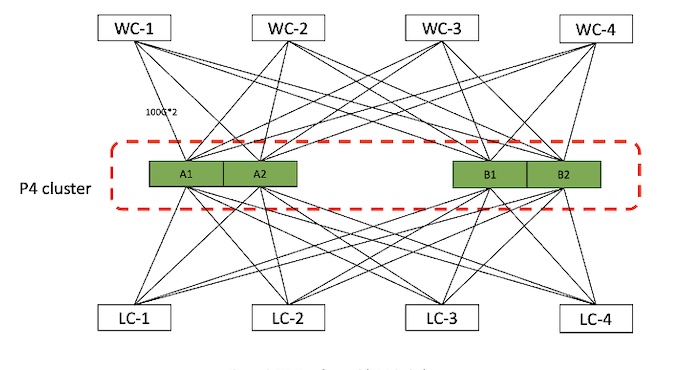
- Lower Cost: With programmable switches, the cost is approximately 60% of the original solution. At present, the bandwidth capacity of one programmable switch is equivalent to the bandwidth capacity of four servers. In terms of cluster construction, the original 8 servers can be replaced by 4 switches, the rule capacity remains unchanged, and the bandwidth capacity is twice the original.
- Higher Performance: The forwarding performance of the Intel® Tofino™ chip can reach the speed limit of 256 bytes of small packets, and the forwarding capability of the whole machine is about 1Tpps. This performance is much higher than the original CPU-based software implementations.

Figure 2 – EIP Topology with P4 Switches
Compared with the X86 cluster gateway device, the architecture of the P4 programmable switch gateway is relatively simple. The main differences are:
- Reduced network layers: directly connect the core switches (WC and LC) of the internal and external networks, skip the access switch TOR.
- Single machine 800G service forwarding capability
- 8*100G uplink 4 WC switches
- 8*100G downlink 4 LC switches
At present, the switch has 32 100G ports, which can support forwarding capabilities from 3.2T to 6.4T. We only use 16 ports of the available ports, mainly to match the rule capacity and bandwidth. The rule capacity of the switch is the bottleneck, and the bandwidth is abundant. When the rule capacity reaches the bottleneck, adding network ports to expand the bandwidth will not only fail to improve the overall rule capacity, but will lead to a waste of network ports.
The P4 programmable switch gateway, directly connected to the core of the internal and external networks, replaces the position of the TOR switch, reduces the network level, reduces the network complexity, and saves the construction cost. Under the same specifications, the machine cost can be reduced by half. At the same time, the scalability and disaster recovery capabilities of the original X86 cluster are retained. The specific cluster capacity can be expanded on demand according to business and disaster recovery requirements. Two or more units can be used to set up a cluster.
Region EIP Flow Processing
Control Plane
We divide the gateway function into two major levels, the control plane and the data plane. The control plane is responsible for the configuration management and state transition of services on the switch, generates and maintains data forwarding rules, and focuses on flexibility and scalability. The data plane transforms and filters specific packets according to the rules issued by the control plane, focusing on the function and performance of packet processing.
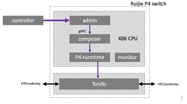
Part of the control plane of Region EIP is deployed centrally, and the other part is distributed on each device. After receiving the business requests issued by the product cluster management and control system, these requests are converted into a set of entries and commands on the P4 switching chip and sent to the Tofino. At the same time, they are also actively or passively collected and summarized according to the requirements of the control system, convert the statistical information on the device (such as EIP traffic, port status, resource utilization, etc.) to the specified service for processing, like monitoring, billing, etc. The whole logic is shown in figure 3 shown below, as shown in the gray block diagram.

Figure 3 – Region EIP with Tofino
- The ‘controller’ represents the gateway cluster management and control system (the real system will be more complicated than this, here the controller refers to the whole control system). The ‘controller’ issues rules, such as creating a new EIP and specifying its bound CVM (cvm’s vpc id, host, vpc ip address, etc.).
- Admin/composer/P4-runtime is the control logic working on the local X86 CPU, which is sent to Tofino through the interface of P4-runtime. The control logic is divided into these three layers for compatibility with existing designs and expansion of new hardware. As the middle layer, the ‘composer’ connects to the original admin interface and the P4 runtime interface, it performs rules and resource management (e.g. the management of resources such as meters and counters on the chip), and follows up on the EIP rules issued by the admin and converts them into corresponding entries on the chip.
Data Plane
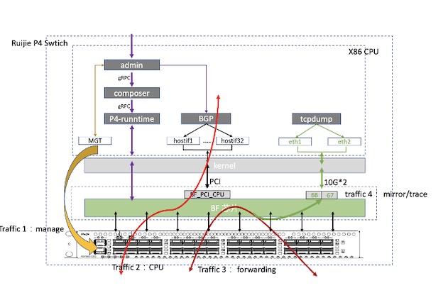
From the perspective of business usage, we divide the traffic of the switch into four categories:
- Management port traffic: This part of the traffic directly enters the X86 CPU system on the switch for processing through the management port on the front panel, without going through the Tofino switch chip. This part of the traffic processing process is not much different from the traffic on the server, but the device form is changed from a server to a switch. The default route of the switch is also configured on this port.
- CPU traffic: The traffic on some CPUs needs to be sent and received through the Tofino port. For example, we declare the EIP network segment through BGP.
- Service forwarding traffic: EIP sending and receiving, conversion, and encapsulation are all carried out by Tofino.
- Service monitoring mirror traffic: When operation and monitoring track a certain EIP, the mirror traffic is forwarded to the corresponding mirror port.

Figure 4 – EIP Data Plane
Tofino carries the service traffic of the latter three scenarios. The data plane flow processing in Tofino is divided into two parts: Platform switch and EIP service.

Figure 5 – Data Plane Running in Tofino
The EIP business module refers to the part of the business logic unique to the Region EIP such as the EIP conversion (overlay information and underlay information) function. This module not only requires functions, but also has high requirements for capacity and performance. The main business logic of Region EIP can be divided into:
- EIP service: For incoming packets, extract the VPC information corresponding to CVM according to the destination IP, and store it in metadata. For outgoing packets, verify the correctness of the encapsulation and remove the outer GRE tunnel.
- Rate-limiting statistics: For inbound packets, rate-limiting and traffic statistics are performed according to EIP. For outgoing packets, the EIP is first searched according to the tunnel information and inner source IP, and then rate-limiting and statistics are performed.
- Tunnel Encapsulation: Unlike traditional switches, we do not use a complete routing table and neighbor forwarding table here. Instead, a port mapping table is used to map the ports in the inbound and outbound directions one-to-one。Construct the GRE header according the metadata. These mapping relationships are filled in the port mapping table by the CPU according to the system neighbor table information when the system is initialized.
The platform switch module is relatively loose with the business, and can be reused by other gateway devices in the future. This part of the function includes packet mirroring, CPU packet processing, etc. Taking CPU processing as an example, it forward the packets coming from the CPU to Tofino. In reverse, it classifies and filters the packets received in Tofino, identifies packets to the CPU, and forwards them to the CPU port. This part of the function is abstracted into code common to multiple businesses, shared by multiple products.
In the whole process, each message has a predefined metadata information, which is used to cache query results, such as output port index number, GRE message field, etc. Finally, the tunnel module will encapsulate the outer GRE header according to the metadata and send. Sometimes abnormal packets or configuration errors cause packet search failure or packet loss when the rate exceeds the limit. Various types of exceptions will be counted before the discard policy is applied.
Improvement Suggestions for Tofino
We also encountered some design limitations of Tofino itself.
- Internal Memory Resource is small: No matter the capacity of on-chip SRAM or TCAM, it is not comparable with the X86 server. SRAM per single pipeline is 10+MB memory. These capacities are spread across different stages, which further limits our usage.
- Packet fragmentation support is not friendly: There is some solution in Tofino for packet fragmentation with on-chip MAU ALU. However, the solution is not so flexible and has limitations to keep the same packet length for fragmentations.
Abbreviation Index
TGW: Tencent Gateway
EIP: elastic IP
CLB: Cloud Load Balancer of Tencent Cloud
CVM: Cloud Virtual Machine
WC: core switch connected to internet network
LC: core switch connected to IDC local network
XGWW: tor switch for TGW to connect WC switch
XGWL: tor switch in IDC local network, connect to LC switch