The Aether platform brings together multiple ONF projects to create a solution for private 4G/5G mobile connectivity. The User Plane Function (UPF) is a fundamental piece of the mobile core network architecture. It is a specialized router that handles all user-generated traffic to and from the radio base stations. In this post, we focus on how P4-programmable switches are used as part of the SD-Fabric project to realize a UPF capable of meeting the low latency and high bandwidth requirements of enterprise Industry 4.0 use cases – this is the P4-UPF. Today, P4-UPF is operational and deployed at several sites worldwide as part of the Aether network.
Software vs. Hardware UPF
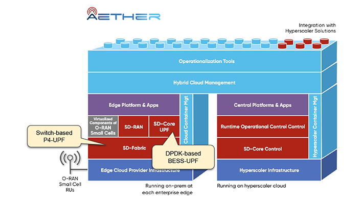
Figure 1: Aether Architecture
There are multiple options for implementing a UPF, each with pros and cons. A popular method is implementing the UPF in software as a user space application. This approach offers many advantages in terms of deployment flexibility and horizontal scalability. For example, the ONF’s SD-Core project, which Aether uses to realize a 4G/5G disaggregated mobile core, by default runs with a cloud-native containerized UPF based on DPDK and the Berkeley Extensible Software Switch (BESS). We call this the BESS-UPF. Containerization enables new instances of BESS-UPF to be brought up quickly on any server managed by Kubernetes. However, the flexibility of relying on general-purpose CPUs usually comes with a higher cost per unit of throughput. The higher the bandwidth required, the more CPU resources need to be dedicated to UPF processing, resulting in higher operational and capital costs due to increased CPU power consumption and the need to buy and manage more servers to fit other edge applications. Moreover, with a software-based implementation it is harder to provide low latency and jitter deterministically.
To reiterate, in Aether, we mainly focus on private 4G/5G connectivity for edge clouds, targeting enterprise and Industry 4.0 use cases. In selecting to use switching hardware to implement P4-UPF, it’s helpful to decompose the previous sentence:
- Enterprise and Industry 4.0 use cases: a strong focus on IoT and AI/ML-enabled automation applications which often require significantly lower latencies and highly predictable very low jitter.
- Edge clouds: an infrastructure comprising one or more servers deployed at the enterprise premise, connected to base stations and upstream routers using fabric switches. In Aether, we use switches based on the Intel® Tofino™ chip, which can be programmed using the P4 language to perform functions well beyond traditional bridging and routing.
- Private 5G connectivity: the goal is to provide connectivity within an enterprise at a smaller scale (compared to a telco macro-cell deployment) optimized for the enterprise’s needs.
To summarize, given the performance requirements, availability and advantages of programmable switches, we provide the ability to process targeted workloads and use cases in a UPF that has been moved from servers to switches to obtain higher performance and reduced load on server CPUs.
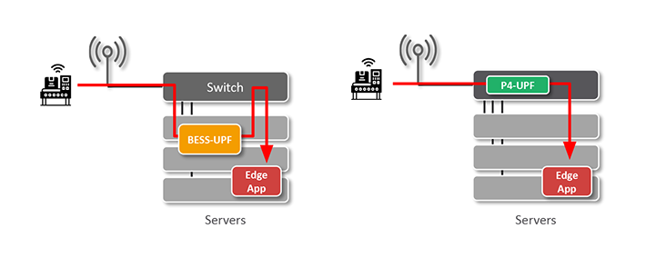
Figure 2: Single-rack Aether Edge with BESS-UPF vs. P4-UPF
The P4-UPF is an integral part of the SD-Fabric project, which aims at realizing an SDN-based programmable fabric platform for the next-generation data center. In SD-Fabric, the UPF runs entirely in hardware as part of the switch P4-defined packet processing pipeline. As a result, we can terminate GTP-U tunnels and perform other UPF functions at the switch line rate, with an aggregate throughput in the order of Terabits per second, with latency below 1.5 microseconds and jitter of around 4 nanoseconds.1
It is important to note that BESS-UPF and P4-UPF are not mutually exclusive. On the contrary, they can be integrated to build a hybrid solution that offers both scale and performance. For example, for use cases that require horizontal scalability, BESS-UPF instances can be spun up on-demand to handle increasing traffic demands, while latency-sensitive and throughput-intensive applications can be offloaded to the hardware fast-path provided by SD-Fabric’s P4-UPF.
Supported P4-UPF Features
Today P4-UPF implements a core set of features capable of supporting requirements for a broad range of enterprise use cases:
- GTP-U tunnel encap/decap: including support for 5G extensions such as PDU Session Container carrying QoS Flow Information, with scalability to tens of thousands of uplink and downlink tunnels.2
- Accounting: P4 is used to flexibly define switch counters required to support usage reporting and volume-based triggers.
- Downlink buffering: when a user device radio goes idle (power-save mode) or during a handover, switches are updated to forward all downlink traffic for the specific device (UE) to a K8s-managed buffering service running on servers. Then, when the device radio becomes ready to receive traffic, packets are drained from the software buffers back to the switch to be delivered to base stations.
- QoS: support for enforcement of maximum bitrates (MBR), minimum guaranteed bitrates (GBR, via admission control), and prioritization using switch queues and scheduling policy.
- Slicing: multiple logical UPFs can be instantiated on the same switch, each one with its own QoS model and isolation guarantees enforced at the hardware level using separate queues.
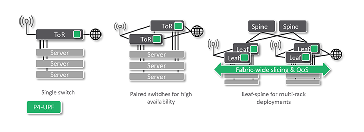
Figure 3: In multi-switch topologies, all leaves are programmed to terminate GTP-U tunnels
In SD-Fabric (and therefore in Aether) we support different edge deployment sizes: from a single rack with just one Top-of-Rack (ToR) switch, or a paired-ToR for redundancy, to NxM leaf-spine fabrics for multi-rack deployments. For this reason, P4-UPF is realized with a “distributed” data plane implementation where all leaf (ToR) switches are programmed with the same UPF state, such that any leaf can terminate any GTP-U tunnel. This provides several benefits:
- Simplified deployment: base stations can be connected via any leaf switch.
- Minimum latency: the UPF function is applied as soon as packets enter the fabric, without going through additional devices before reaching their final destination.
- Fast failover: when using paired-ToRs, if one switch fails, the other can immediately take over as it is already programmed with the same UPF state.3
- Fabric-wide slicing & QoS guarantees: packets are classified as soon as they hit the first ToR. We then use packet marking to enforce the same QoS rules on all hops. In case of congestion, flows deemed high priority are treated as such by all switches.
Architecture and Integration with SD-Core
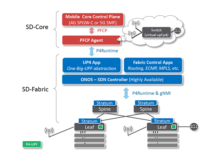
Figure 4: Control plane architecture of P$-UPF in SD-Fabric
P4-UPF builds upon the SD-Fabric architecture. We use Intel® Tofino™-based white box switches running Stratum and controlled by the ONOS SDN controller. On top of ONOS, there are two sets of applications, each one responsible for managing different switch tables:
- The Fabric Control Apps: in charge of bridging, IPv4 and IPv6 routing, ECMP, MPLS segment routing (if the topology includes spines), re-routing in case of failures, learning routes via OSPF/BGP, DHCP relay, and more.
- The UP4 App: in charge of populating the UPF tables while providing integration with standard 3GPP interfaces via a “One-Big-UPF” abstraction.
The interface between the mobile core control plane and the UPF is defined by the 3GPP standard Packet Forwarding Control Protocol (PFCP). This is a complex protocol that can be difficult to understand, even though at its essence the rules that it installs are simple match-action rules. The implementation of such protocol, such as message parsing, state machines, and other bookkeeping can be common to many different UPF realizations. For this reason, we created a dedicated component, PFCP Agent, which is shared by P4-UPF and BESS-UPF.
Communication between the PFCP Agent and the UP4 App is done via the much simpler gRPC-based P4Runtime API, a generic interface for populating match-action tables and managing other pipeline constructs defined in P4. This is the same API the UP4 App uses to communicate with the switches. However, in the former case, it is used between two control planes, the mobile core, and the SDN controller. Leveraging P4Runtime at the control plane seemed the most natural choice, as the goal of the UP4 App is that of abstracting the whole fabric as one virtual big switch acting as a UPF.
This is a pattern common in SDN: the One-Big-UPF abstraction allows the upper layers to be independent of the underlying physical topology. The deployment can be scaled up and down, adding or removing racks and switches, without changing the mobile core control plane, which instead is provided with the illusion of controlling just one switch. The “One-Big-UPF” abstraction is realized with a virtual-upf.p4 program that formalizes the forwarding model described by PFCP as a series of match-action tables. This program doesn’t run on switches, but it’s used as the schema to define the content of the P4Runtime messages between PFCP Agent and the UP4 App. On switches, we use a different program, fabric.p4, which implements tables similar to the virtual UPF but optimized to satisfy the resource constraints of Tofino, as well as tables for basic bridging, IP routing, ECMP, and more. The UP4 App implements a P4Runtime server, like if it were a switch, but instead it internally takes care of translating P4Runtime rules from virtual-upf.p4 to rules for the multiple physical switches running fabric.p4, based on an up-to-date global view of the topology.
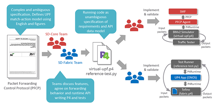
Figure 5: Development process between SD-Fabric and SD-Core teams. P4 is used as the lingua franca to agree on how UPF features should be realized
Finally, using P4 to define a virtual UPF serves another important benefit: it drastically improves development processes between different teams. At ONF, in the past year, P4 has become the lingua franca between the SD-Core and SD-Fabric teams. At the beginning of the Aether project, we spent a lot of time trying to agree on how packets should be processed. Like most other specification documents, PFCP defines operations on packets using the English language and figures, leaving room for ambiguity and misinterpretation. To solve this problem, today we write P4 code (virtual-upf.p4) and packet-based unit tests to formally agree on how features should be realized, after which teams can work independently. The SD-Core team relies on the reference virtual-upf.p4 program running on the BMv2 software switch simulator to test changes in their control plane software. On the other side, the SD-Fabric team uses the reference tests to validate changes to the Tofino P4 program (fabric.p4) and the UP4 App in ONOS.
Further reading:
Check out this paper to learn more about how we used P4 to implement a UPF:
R. MacDavid et al. A P4-based 5G User Plane Function, SOSR 2021
Enhanced Visibility with INT
SD-Fabric includes scalable support for Inband Network Telemetry (INT) providing unprecedented visibility into how the network processes individual packets. When using INT, each switch is programmed such that:
- For each flow (5-tuple), it produces periodic report packets to monitor the path in terms of hops, ports, queues, and end-to-end latency.
- When packets get dropped, it generates reports carrying the drop reason (e.g., routing table miss, TTL zero, queue congestion, and more).
- During congestion, it produces enough reports to reconstruct a snapshot of the queue at a given time, making it possible to identify which flow is causing delay or drops to other flows.
By running the UPF as part of the switch with INT support and by correlating INT analytics with information from the mobile core control plane, we can validate SLAs for QoS metrics and provide better troubleshooting. For example, thresholds can be defined to immediately generate an alert if a packet from a high-priority IoT sensor is experiencing high latency due to congestion, or worse if it gets dropped. Alarms from INT reports can be used to trigger human intervention to troubleshoot and fix the issue or can be plugged in with closed-loop control systems such as those being developed as part of Project Pronto.
Moreover, the integration between the UPF and INT functions improves issue localization. For example, when processing GTP-U encapsulated packets, we can “watch” inside GTP-U tunnels, generating reports for the inner headers and making it possible to troubleshoot issues at the application level. In addition, when generating drop reports, we support UPF-specific drop reasons to identify if packets are getting dropped by one of the UPF tables (because of a bug somewhere in the control stack, or simply because the specific user device is not authorized), or if they are being dropped for some other reason.
What About SmartNICs?
SmartNICs are a hot topic right now and certainly an appealing option to offload infrastructure tasks from CPUs. In contrast to solutions based on full or partial SmartNIC offload, SD-Fabric’s switch-based P4-UPF does not require additional hardware other than the same switches used to interconnect servers and base stations. However, for small edge cloud deployments where the cost and space required for a high-performance programmable ToR switch is not justified, offloading the UPF to SmartNICs may be a better option to meet the low latency and high throughput requirements. For those deployments, support for SmartNICs is on the roadmap for Aether and SD-Fabric.
Conclusions
In Aether, P4 is leveraged to realize a high-speed UPF datapath that runs entirely in hardware as part of the switch packet processing pipeline. When compared to software-based implementations, SD-Fabric’s switch-based P4-UPF offers significantly lower latency and jitter, making it easier to meet the requirements of enterprise and Industry 4.0 use cases, while reducing costs by freeing up CPU resources and making them available to edge applications.
P4-UPF will be released as part of SD-Fabric v1.0, which is due at the end of September. It will include support for traditional 3GPP features, including integration with the 4G/5G mobile core control plane via a standard PFCP interface, as well as advanced features such as fabric-wide QoS and slicing, and enhanced visibility with INT.
_____________________________________
1 These numbers are implementation-specific and might not represent the hardware capabilities.
2 This number is not final. If needed, scale can be increased by further optimizing the pipeline design and by using techniques such as Tofino pipeline folding.
3 UPF fast failover assumes dual-homing for servers and base stations, or a single-homed base station with the mobile core control plane integration triggered handovers upon switch failure.
Intel, the Intel logo, and Tofino are trademarks of Intel Corporation or its subsidiaries.